Computer Arithmetics - Adder

Ripple Carry Adder
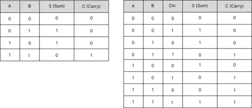
Consider we have two binary bits \(x\) and \(y\) and we want to add it together. The full adder and half adder is utilized as a building block. A half adder has two input bits \(x\) and \(y\) and produce a sum bit \(s = x \oplus y\) and a carry bit \(c = xy\). A full adder receives three input \(x\), \(y\) and \(c_{in}\) where \(c_{in}\) is carry input from the previous adder. The output from full adder also has two outputs \(s = x \oplus y \oplus c_{in}\) and \(c_{out} = xy \vee xc_{in} \vee yc_{in}\). This operand is the adder for just only 1 binary bit. The truth table for the half adder and full is shown.
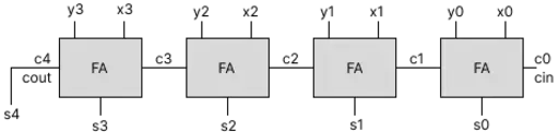
Fundamentally, to build k-bit adder, a k-bit ripple carry adder required k FAs by cascading the FA k block each other. It is resulting in k-bit sum bit and k+1-bit carry bit. Assume we have two 4 bit binary \(x\) and \(y\) where \(x=x_3x_2x_1x_0\) and \(y=y_3y_2y_1y_0\). The block diagram of this 4-bit ripple carry adder (RCA) is shown in figure below. It shows that the RCA produce a 4-bit sum or 5-bit sum where the MSB is the carry output of the last FA.
The critical path of the ripple carry adder can be considered from the first input to the final output where it passthrough the carry chain. The latency can be break down into three path: the path from input to carry, the path from carry in to carry out and the path from carry in to output. The path from carry in to carry out is the longest path in the block diagram and it passthrouth \(k-2\) FA. As the latency approximate, we can say that the latency of a ripple-carry adder is \(kT_{FA}\) where \(T_{FA}\) is the latency of an FA.
Analysis of Carry Propagation
Since the length of the carry chain depends on the number of digit when perform adding, the average length of the worst-case carry chain in a k-bit addition is interested to explore. Assume an adder operation is performed, for each position \(i\) we have
- The probability of carry generation is 0.25. (Both is 1)
- The probability of carry annihilation is 0.25. (Both is 0)
- The probability of carry propagation is 0.5. (It is different.)
From the analysis, the average length of the longest carry chain in k-bit addition is approximate to \(\log_2k\) and suggest that \(\log_2(1.25k)\) is a better estimate.
Adder as building blocks
Assume that we have 4-bit RCA, and we will build some designs from it: A multiply-by-5 circuit and squaring circuit for a 2-bit binary number.
To implement a multiply-by-5 circuit based on 4-bit unsigned RCA \(X\), we need to compute
\[Y = 4X + X\]We will use a 4-bit binary adder:
- Compute \(4X\) by left-shifting \(X\) by two bit.
- Add \(X\) and \(4X\) using the 4-bit adder.
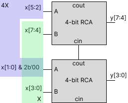
The block diagram is shown above. The leftshift is simply by organizing bit by adding zero bit to LSB. There are two RCAs for first and second half of the binary number. Then, two number are added using RCA resulting in \(Y\). The keyidea of this circuit is shifting and adding.
To compute the square of a 2-bit binary number \(x = (x_1x_0)\) using a 4-bit adder, we will follow a structured approach using shift-and-add multiplication. We will expressing \(x^2\) in terms of partial products. We can write
\[x^2 = (x_1x_0) \times (x_1x_0)\] \[x^2 = (2x_1 + x_0) \times (2x_1 + x_0)\] \[x^2 = 4x^2_1 + 4x_1x_0 + x^2_0\]Now, let’s compute each term using shifting and addition. First, to compute \(4x^2_1\), the shifting left by two bit is down for multiply by 4. Since the result from the square is 1 or 0 (1-bit binary number), there is no need to compute the square. Again, compute \(4x_1x_0\) can be done by logical and gate and left shifting. It is the same methology for \(x^2_0\). Thus we get,
\[x^2 = (x_1 << 2) + (x_1x_0 << 2) + (x_0)\]Then, we can use RCA to add these two terms.
Carry-Lookahead Adders
The ripple carry adder has its latency grow at least linearly with the word width k. The carry-lookahead adder can add two k-bit binary number in logarithmic growth. CLA try to lookahead the carry chain by producing the generate, propagate and annihilate or transfer signal, \(g_i, p_i, a_i\) and \(t_i\) respectively. These signal is produced as follow:
- Carry is generated \(g_i = x_i y_i\).
- Carry is propagated \(p_i = x_i \oplus y_i\).
- Carry is not annihilated \(t_i = \bar{a} = g_i \vee p_i\).
These signals, it produce the carry bit: \(c_{i+1} = g_i \vee p_ic_i\). For example, if we have k=4, the logic of carry is expressed as follows:
\[c_1 = g_0 \vee c_0p_0\] \[c_2 = g_1 \vee g_0p_1 \vee c_0p_0p_1\] \[c_3 = g_2 \vee g_1p_2 \vee g_0p_1p_2 \vee c_0p_0p_1p_2\] \[c_4 = g_3 \vee g_2p_3 \vee g_1p_2p_3 \vee g_0p_1p_2p_3 \vee c_0p_0p_1p_2p_3\]The \(c_0\) and \(c_4\) are the input and output of the adder. The sum bit is produced parallely from the input with the carry generation as mensioned above.
Example Latency Analysis for CLA
- For a 4-bit CLA, the critical path typically involves 4 “AND” gates and 1 “OR” gate in series, giving about 5 gate delays to compute the final carry-out.
- Extending this to a 16-bit adder by cascading four 4-bit CLAs results in 9 gate delays on the carry path.
In general, the latency of a CLA can be approximated by: \(T_{\mathrm{CLA}} \approx 4 \,\log_{4} k + 1,\) which is \(O(\log k)\), rather than \(O(k)\) for the RCA.
Key takeaways
- Ripple Carry Adder (RCA):
- Latency grows linearly with \(k\).
- Average carry-chain length is about \(\log k\), though the worst case is still \(k\).
- Hardware cost is relatively small.
- Carry-Lookahead Adder (CLA):
- Latency grows approximately \(\log k\).
- Hardware cost (e.g., transistor count) is higher than an RCA.
- By precomputing carry-propagate and carry-generate signals, it reduces the delay significantly compared to an RCA.
Thus, designing faster adders often involves trading off area/power (more hardware) for speed (lower latency), moving from linear-time adders (RCA) to logarithmic-time solutions (CLA).
Acknowledgement
The keypoint is taken from the Behrooz Parhami’s lecture and they are very helpful on computer arithmetics.
Related Posts: